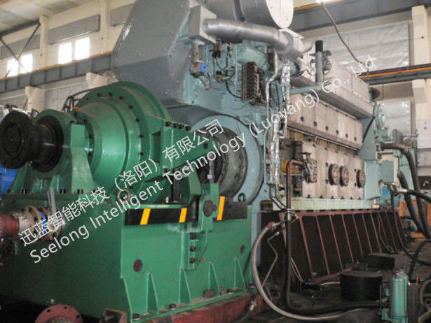
SHD120-2000/7500 Compact Assembly hydraulic dynamometer For Engine test
Technical specifications
1.Main features
◆Small size, easy installation;
◆Simple structure, easy operation and maintenance;
◆High braking moment;
◆High accuracy of measurement;
◆Work stably and reliably;
◆Achieving High Precision Instantaneous Speed Measurement with Magnetoelectric Velocity Sensor;
◆Fast Load Control of Electronically Controlled Butterfly Valve;
◆Fast response, suitable for dynamic test
Technical Parameters

Characteristic curve
Product Describe
SHD120-2000/7500 is a compact assembly hydraulic Dynamometer. It is a high speed and low inertia solution with extremely low maintenance cost, ideal to test engines with power up to 120 kW and speed up to 7500 rpm.
Use of dynamometer
1. Before boot
(1) Loosen the bolt of the sensor protection device to make the stator free.
(2) Check the connection between coupling and spindle.
(3) Check the coaxiality of the power machine and dynamometer.
(4) Check the connection and circulation of the inlet and outlet pipe systems.
(5) Clean the appearance, add lubricating oil to each lubrication point, and rotate the spindle to check whether the rotor and other components have collision and rotation inflexibility.
(6) The calibration meets the requirements.
(7) Fully open drainage butterfly valve (minimum load position).
2. Start-up test
(1) Start the power machine to drive the dynamometer spindle to rotate at the same speed. After the power machine is running normally, the test can be carried out.
(2) Fully open the intake valve and adjust the opening of the drainage butterfly valve until it is consistent with the working condition of the power engine.
(3) Four control modes, namely, constant position, constant torque, square torque and constant speed, can be selected to control the electronic control cabinet matched with dynamometer in the test of engine external characteristics, speed regulation characteristics, load characteristics and other characteristics.
(4) For some engines, sometimes the water supply pressure of a fixed dynamometer can not meet the test requirements of all working conditions, which can adjust the water supply pressure properly under different test conditions.
3. End of the experiment
(1) Close the intake valve.
(2) Fully open drainage valve.
(3) The engine runs at low speed for several minutes and then stops.
(4) Rotary sensor protection device, so that the stator is locked, the sensor is not forced.
(5) Cut off the power supply connected with the electronic control cabinet.
(6) Stop lubricating system oil supply.
(7) If the test is not done for a long time, the bottom drain valve of dynamometer should be opened to remove the accumulated water. If conditions permit, the upper end of the shell screw can be unscrewed and the accumulated water can be purged with compressed air.
In order to prevent bearing from entering water, please remember!!! The principle of "first start, then drain; first shut down, then shut down". To ensure that the dynamometer in the rotating state of water, but also should prevent the dynamometer in the anhydrous state of continuous operation for too long and burnt the sealing parts. (Require anhydrous working time is not more than 2 minutes.)

 Your message must be between 20-3,000 characters!
 English